

PWM vs. MPPT
MPPT is the new rage on solar charge controllers, but does this end up being overkill for your camping trailer? Everyone likes the Royal Royce choice, but is the MPPT wasted energy in smaller camping solar systems? The MPPT is made for larger home systems where the additional 20% or more energy harvesting is worthwhile.
The MPPT has a heat sink that radiates large amounts of heat that is energy from the solar panels. The extra energy goes out in heat. The heat represents lost energy or power that did not make it to the battery. Because of this heat, you cannot install the MPPT controller in your trailer wall because they require airflow.
The PWM is a good option for smaller systems monitoring the solar panels’ inconsistent current, outputting a consistent voltage to the battery which allows the battery to reach maximum capacity and extending the life of the trailer batteries.
As referenced by: https://www.solar4rvs.com.au/buying/buyer-guides/choosing-the-right-solar-charge-controller-regulat/
“The crux of the difference is:
- With a PWM controller the current is drawn out of the panel at just above the battery voltage, whereas
- With an MPPT controller the current is drawn out of the panel at the panel “maximum power voltage” (think of an MPPT controller as being a “smart DC-DC converter”).
You often see slogans such as “you will get 20% more energy harvesting from an MPPT controller”. This extra actually varies significantly and the following is a comparison assuming the panel is in full sun and the controller is in bulk charge mode. Ignoring voltage drops and using a simple panel and simple math as an example.
Panel Maximum Power Current (Imp)
Panel Maximum Power Voltage (Vmp)
Battery voltage -13V (battery voltage can vary between say 10.8V fully discharged and 14.4V during absorption charge mode). At 13V the panel Amps will be slightly higher than the maximum power Amps, say 5.2A.
With a PWM controller the power drawn from the panel is 5.2A* 13V= 67.6 watts. This amount of power will be drawn regardless of the temperature of the panel, provided that the panel voltage remains above the battery voltage.
With an MPPT controller the power from the panel is 5.0A *18V = 90 watts, i.e. 25% higher. However this is overly optimistic as the voltage drops as the temperature increases, so assuming the panel temperature rises to say 30°C above the standard test conditions (STC) temperature of 25°C and the voltage drops by 4% for every 10°C, i.e. total of 12% then the power drawn by the MPPT will be 5A *15.84V=79.2W i.e. 17.2% more power than the PWM controller.
In summary, there is an increase in energy harvesting with the MPPT controllers, but the percentage increase in harvesting varies significantly over the course of the day.
The difference in the operations is:
A PWM (Pulse Width Modulation) controller can be thought of as an (electronics) switch between the solar panels and the battery:
- The switch is on when the charger mode is in bulk charge mode
- The switch is “flicked” on and off as needed (pulse width modulated) to hold the battery voltage at the absorption voltage
- The switch is off at the end of absorption while the battery voltage drops to the float voltage
- The switch is once again “flicked” on and off as needed (pulse width modulated) to hold the battery voltage at the float voltage
Note that when the switch is off the panel voltage will be at the open circuit voltage (VOC) and when the switch is ON the panel voltage will be at the battery voltage + voltage drops between the panel and the controller.
The best panel match for the controller is a panel with a voltage that is just sufficiently above that required for charging the battery and taking temperature into account, typically, a panel with a Vmp (Voltage Max Power) of around 18V to charge a 12V battery. These are frequently referred to as a 12V panel even though they have a Vmp of around 18V.
The MPPT controller could be considered to be a “smart DC-DC converter”, i.e. it drops the panel voltage (hence “grid tie” could be used) down to the voltage required to charge the battery. The current is increased in the same ratio as the voltage is dropped (ignoring heat losses in the electronics). Just like a conventional step-down DC-DC converter.
The “smart” element in the DC-DC converter is the monitoring of the maximum power point of the panel which will vary during the day with the sun strength and angle, panel temperature, shading and panel(s) health. The “smart” they adjust the input voltage of the DC-DC converter is the monitoring of the maximum power point of the panel which will vary during the day with the sun strength and angle, panel temperature, shading and panel(s) health. The “smart” then adjusts the input voltage of the DC-DC converter – in “engineering speak” it provides a matched load of the panel.
The best panel match for the MPPT controller:
To match a panel to an MPPT controller it is advisable to check the following:
- 1.The panel open circuit voltage (VOC) must be under the permitted voltage.
- 2.The VOC must be above the “start voltage” for the controller to “kick-in”
- 3.The maximum panel short circuit current must be within the range specified
- 4.The maximum array wattage – some controller allow this to be “over-sized”.
So how do you chose the right controller for your trailer?
The PWM is a great low-cost option:
- For smaller systems
- Where the efficiency of the system is not critical.
- For solar panels with a maximum power voltage (Vmp) of up to 18V for charging a 12V battery The
MPPT controller best:
- For larger systems where the additional 20% or more energy harvesting is worthwhile
- When the solar array voltage is substantially higher than the battery voltage e.g. using house panels for charging 12V batteries.”
So when it comes to purchasing a solar charge controller for the solar system for your camping trailer, the MPPT may sound good but chose wisely, look for the best option for your application!”
Atkinson Electronics PVCM40D-MPT is a 40Amp charge controller that uses Multi Point Tracking (MPT) that uses Pulse Width Modulation (PWM).
- The MPT continuously reads the voltage during each of the charging stages to account in change for battery loads.
- PWM monitors the solar panels’ inconsistent current and outputs a consistent voltage to the battery.
MPT That Uses PWM - 6 Stages
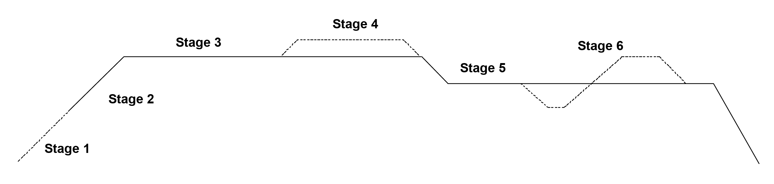
Stage 1 - Soft Charge
When the batteries are discharged below 10.5VDC, the controller will softly ramp up the charge rate until the battery voltage reaches 10.5VDC at which point it will enter the bulk charge stage. (Battery status LED blinks red, charge type & charge mode LEDs will be lit red).
Stage 2 - Bulk Charge
Maximum charge current from solar panels is applied to the battery(s) until it reaches the absorption voltage threshold for your battery type selected on DIP switches 1&2. (Charge mode LED will be solid red).
Stage 3 - Absorption Charge
The battery voltage is maintained at a constant voltage using PWM technology to finish charging the battery(s) to 100% of charge.
The controller uses Multi Point Tracking (MPT) to compensate for changing loads and solar conditions to maintain constant charge rate. (Charge mode LED will blink red).
Stage 4 - Battery Equalization Charge
Battery equalization is only available for (wet) flooded lead acid battery(s). Battery equalization automatically occurs when the battery voltage has dropped below 12.1VDC for the third time within a 14 day period or once in a 28 day period. The controller blinks the charge type LED blue when the equalization flag is set, and will run the equalization routine once the conditions are met, to bring the internal cells of the battery to an equal state to reverse the loss of capacity due to being discharged below 12.1VDC.
Red: Charge mode
Blink Red: Absorption charge
Blue: Equalization charge
Stage 4a – Lifeline Conditioning Charge
Lifeline batteries can be conditioned if the total Imp. from the solar panels is greater than 10 Amps. The PVCM40D-MPT monitors the solar charge Amps during the Bulk charge stage, if 10+ Amps was detected it sets the 10 Amp Flag. The controller also monitors the battery voltage over a 14 to 21 day period, if the battery voltage drops below 12.1VDC three times in that period or fails to finish the absorption charge before end of day during that period it sets the conditioning flag. At the end of the 21 day period the controller must see 10+Amps of charge current during the Bulk charge and complete the full charge cycle before it begins a conditioning cycle. If the panels don’t produce 10+Amps during the bulk charge the conditioning charge is not activated that day and will try again during the next day’s charging cycle. Conditioning will only occur once in a 21 - 28 day period.
Stage 5 - Float Charge
The batteries are fully charged at this point and are maintained at a safe voltage level. During the float charge the controller is constantly adjusting its PWM control to adjust for varying solar charging currents and trailer loads to maintain a float voltage of 13.5VDC for sealed/gel batteries and 13.7VDC for lead acid & AGM batteries.
Green: Charge mode.
Stage 6 – Auto Boost Charge
The auto boost feature is as follows: The controller is in float charge, the trailer loads become greater than the solar charging current and the battery voltage is pulled below 13.0VDC for more than 5 minutes. The auto boost flag is set, when the loads are reduced to the point where the float charge returns the battery voltage back to float voltage, the controller then performs a shortened Bulk/Absorptions charge cycle restoring the battery(s) to 100% and then returns to the float charge. Charge type LED will blink magenta when auto boost flag is set and will on continuously during the charge cycle.
Stage 6a – Manual Boost Charge
The PVCM40D-MPT & SEDM6-40 provides the user, the ability to perform a manual boost charge, any time the controller is in the float charge stage when a SEDM6-40 display is used with the MPT controller. The Manual boost feature is not available when using either PVCM4 or SEDM4 displays. To perform a manual boost charge, the charge controller must be in the float stage as indicated on the controller or the display’s charge status LED is green. The operator uses the SEDM6-40 display’s select button to scroll down to the charge status location, then presses and holds the select button until the green LED turns Red. The PWM controller’s charge mode LED changes from green to red and the charge type LED will light magenta in color. When the controller finishes the manual boost charge it returns to the float Stage and the displays charge status LED will turn green.
When the MPT uses the PWM, it allows the controller to charge the batteries to a higher capacity that extend the life of the batteries while supporting 4 different types of trailer batteries:
- Lead acid
- Lifeline AGM
- Standard AGM
- Gel/ Sealed
Chose the best option for your trailer, RV, Motorhome or Yacht so you can relax and begin your fun.